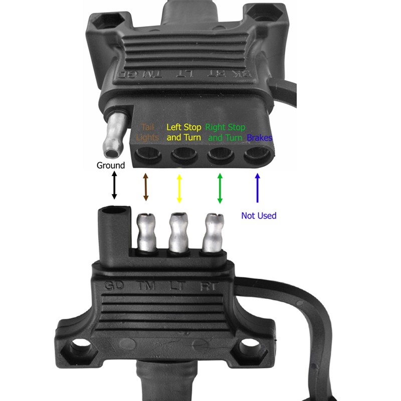
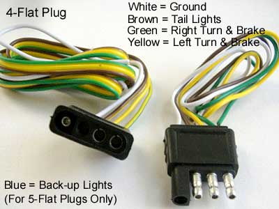
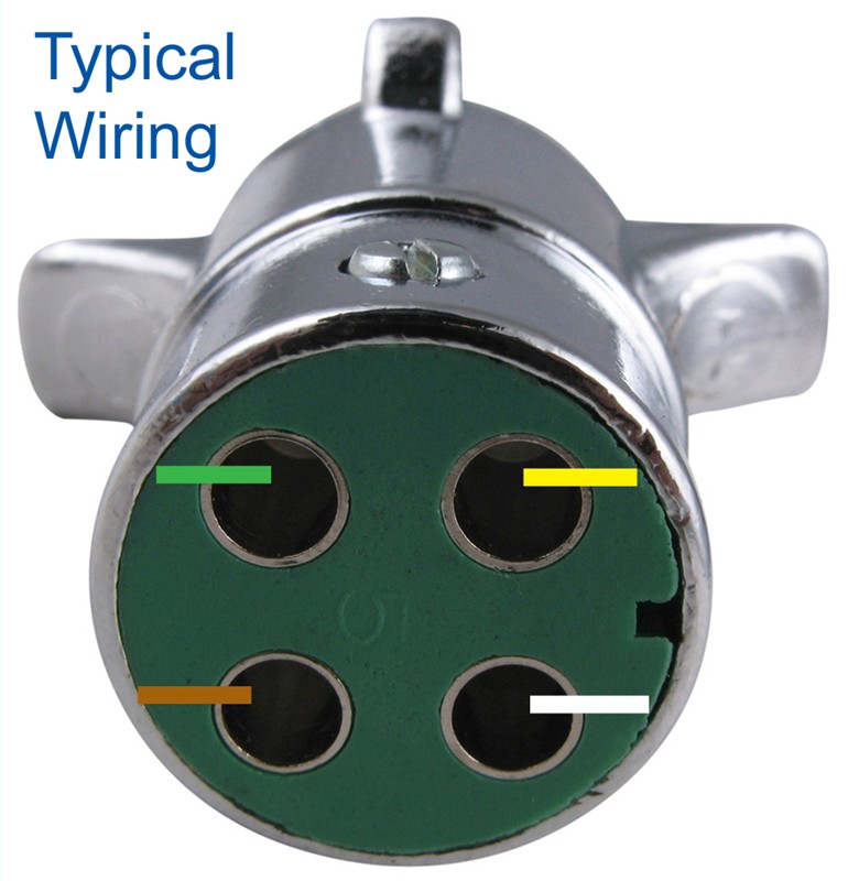
4 Pin Trailer Connector Diagram. The first thing you need to do is make sure that your connector works properly. If you cut the wires off the connector, splice them to the trailer connector, then solder each splice, then seal them with.
A number of ISO standards cover trailer connectors, the electrical connectors between vehicles and the trailers they tow that provide a means of control for the trailers.
Additionally, this connector will mate with all of our Qwiic cables with a solid lock.
The below image and video shows the IC being simulated for all four stages by clubbing in the four input pins of both A and B. Seven-pin connectors are rarely used on trailers for local use. I hope this helps some folks, because it's pretty tough finding this online.


