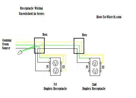
Craftsman riding mower electrical diagram. How to wire an electrical outlet wiring diagram wiring an electrical outlet receptacle is quite an easy jobif you are fixing more than one outlet the wiring can be done in parallel or in series.
 Wire An Outlet
 Electrical wiring for a switch outlet combination.

Electrical wiring diagrams for outlets. Inspirational house wiring plan drawing electrical outlet symbol 2018. Electrical wiring diagram automotive 2018 automotive wiring diagram. How to install electrical outlet and switch combo wiring in most cases the primary power source is shared between the switch and the outlet either with a wire jumper or the bridge or tab that is located on the side of the combo switch and outlet.
Residential electric wiring diagrams are an important tool for installing and testing home electrical circuits and they will also help you understand how electrical devices are wired and how various electrical devices and controls operate. This outlet is commonly used for a heavy load such as a large air conditioner. This wiring is commonly used in a 20 amp kitchen circuit where two appliance feeds are needed such as for a refrigerator and a microwave in the same location.
More about wiring a switched outlet. House electrical wiring diagrams. Wiring a 20 amp 240 volt appliance receptacle.
Steps to take when wiring the electrical outletreceptacle. Here 3 wire cable is run from a double pole circuit breaker providing an independent 120 volts to two sets of multiple outlets. Wiring connections in switch outlet and light boxes.
The following house electrical wiring diagrams will show almost all the kinds of electrical wiring connections that serve the functions you need at a variety of outlet light and switch boxes. The neutral wire from the circuit is shared by both sets. Electrical wiring schematic symbols collections of house wiring circuit diagram pdf home design ideas.
In the diagram below a 2 wire nm cable supplies line voltage from the electrical panel to the first receptacle outlet boxthe black wire line and white neutral connect to the receptacle terminals and another 2 wire nm that travels to the next receptacle. The outlet should be wired to a dedicated 20 amp240 volt circuit breaker in the service panel using 122 awg cable. With this wiring both the black and white wires are used to carry 120 volts each and the white wire is wrapped with electrical tape to label it hot.
Wiring diagram for dual outlets.
 Electrical Code Wiring Diagrams Educamaisvoce Com
  Electrical Wiring Diagram Configuration For 8 Outlets With 1 Gfci
  Gfci Outlet Wiring Diagram Schema Wiring Diagrams
  Residential Outlets Wiring Diagram Cabinetdentaireertab Com
 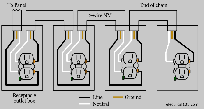 Outlet Wiring Electrical 101
  Wiring A Home Outlet Utahsaturnspecialist Com
  Adding A New Receptacle Outlet At A Switch Diy Electrical Wiring Electrical Wiring Home Office New Electrical Symbol Outlet Unique
 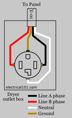 Outlet To Outlet Wiring Machine Repair Manual